





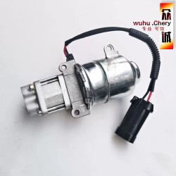




Selespeed Heartbeat Monitor is an open source automotive electronics project designed to monitor hydraulic pump operation in Selespeed and compatible Automated Manual Transmission (AMT) systems.
Powered by an ESP32-C3 microcontroller, the device monitors pump ON/OFF duration, operating cycles and motor current, displaying real-time activity through a circular color TFT gauge with an intuitive heartbeat-style interface.
The project combines embedded electronics, sensor technology and 3D printing to create an affordable monitoring solution that helps drivers and technicians observe hydraulic pump behavior and identify unusual operating patterns for further inspection.
Selespeed Heartbeat Monitor
Open Source AMT Hydraulic Pump Monitoring System
A smart automotive monitoring device powered by ESP32-C3, designed to monitor hydraulic pump activity, operating cycles and motor current in automated manual transmission systems.
1. Introduction
Automated Manual Transmission (AMT) systems use electronic and electromechanical components to control clutch operation and gear shifting. Some systems use a hydraulic unit to generate the pressure required for transmission operation.
One of the important components in these systems is the Hydraulic Pump. Its operating behavior can provide useful information about the condition of the hydraulic system.
Selespeed Heartbeat Monitor is an open source automotive electronics project designed to monitor hydraulic pump activity using an ESP32-C3 microcontroller, Hall-effect current sensor and circular color TFT display.
2. Project Objectives
The project aims to develop an affordable and expandable monitoring device with the following capabilities:
- Detect hydraulic pump ON/OFF status.
- Measure pump operating duration.
- Measure pump OFF interval.
- Count hydraulic pump operating cycles.
- Monitor pump motor current consumption.
- Visualize pump activity using a heartbeat waveform.
- Identify unusual operating patterns.
- Store operating data for trend analysis.
The device is designed for monitoring only. It does not control the transmission ECU, hydraulic pump or gear shifting mechanism.
3. System Architecture
The ESP32-C3 acts as the main processing unit. It receives electrical signals from the monitoring circuits, calculates pump operating parameters and updates the display.
Hardware Components
3.1 ESP32-C3 Controller
The ESP32-C3 is responsible for sensor data acquisition, timing calculations, display control and future wireless monitoring capabilities.
3.2 Circular Color TFT Display
A 1.28-inch circular TFT display using the GC9A01 controller provides a compact automotive gauge interface.
3.3 Hall-Effect Current Sensor
A Hall-effect current sensor, such as a suitable ACS758 variant, measures pump motor current without requiring a high-power shunt resistor in the monitoring circuit.
3.4 Pump Voltage Detection
A protected voltage detection circuit monitors the pump supply signal to determine when the relay supplies power to the pump motor.
3.5 Automotive DC-DC Converter
A protected DC-DC power supply converts the vehicle's electrical supply into a stable voltage for the ESP32-C3 and display.
4. How It Works
The monitoring system uses two main electrical measurements: Pump Voltage and Pump Current.
4.1 Pump ON Detection
When the pump relay supplies electrical power to the motor, the voltage detection circuit sends a signal to the ESP32-C3. The controller starts measuring the pump operating time.
4.2 Pump OFF Detection
When the relay disconnects power from the pump, the controller records the operating duration and begins measuring the OFF interval.
4.3 Current Monitoring
The Hall-effect sensor measures the current consumed by the pump motor. Current measurements can help identify changes in motor operating behavior.
4.4 Cycle Analysis
The controller calculates:
- Pump ON Duration: Time the pump operates.
- Pump OFF Duration: Time between pump operations.
- Cycle Count: Number of pump activations.
- Cycles per Hour: Pump activation frequency.
- Average Operating Time: Average pump ON duration.
- Current Trend: Changes in motor current.
5. Heartbeat Display
The main feature of this project is its heartbeat-style visualization. Instead of displaying only ON/OFF status, the circular gauge provides a visual representation of actual pump activity.
Display Status Indicators
| Status Color | Condition | Description |
|---|---|---|
| GREEN | Normal | Operating pattern is within the configured baseline. |
| YELLOW | Warning | Operating pattern requires attention. |
| RED | Critical | Significant abnormal operating pattern detected. |
| WHITE | Idle | Pump is not operating. |
Information Display
- Pump Status: ON / OFF
- ON Time: Seconds
- OFF Time: Seconds
- Motor Current: Amperes
- Cycle Counter
- System Status Indicator

6. Understanding Hydraulic Pump Behavior
Changes in pump operating frequency and duration may provide useful information about hydraulic system behavior.
For example, an increase in pump activation frequency or unusually long operating duration may indicate a condition that requires further inspection.
Possible Conditions to Investigate
- Hydraulic pressure loss.
- Internal hydraulic leakage.
- Accumulator deterioration.
- Pump motor performance changes.
- Electrical supply or connection problems.
These symptoms are not definitive diagnoses. Pump behavior can also vary with temperature, driving conditions and transmission operation.
7. Open Source Hardware and Software
The project follows an open source development approach to encourage learning, modification and community contributions.
| Project Resource | Description |
|---|---|
| Firmware | ESP32-C3 source code |
| Hardware | Circuit schematics |
| PCB Design | Printed circuit board design files |
| BOM | Bill of Materials |
| 3D Enclosure | Printable STL and CAD files |
| Documentation | Installation and wiring guides |
| Calibration | Sensor calibration instructions |
| Vehicle Profiles | Model-specific configuration |
Source code and hardware design files will be published through the project's GitHub repository when they are ready for public release.
Proposed licenses include MIT or Apache-2.0 for firmware, CERN-OHL-S for hardware design and CC BY-SA 4.0 for documentation. Final licensing will be specified in each published repository.

8. 3D Printed Enclosure
The monitor will use a custom 3D-printed housing designed for compact installation inside the vehicle cabin.
- Circular gauge housing.
- 1.28-inch TFT display mounting.
- ESP32-C3 controller compartment.
- Cable management.
- Screw mounting points.
- Removable rear cover for maintenance.

PETG, ABS or ASA may be considered for prototype and production enclosures. ASA is a preferred candidate for improved UV and heat resistance, subject to temperature testing in the intended installation location.
9. Universal AMT Compatibility
The long-term goal is to develop a universal monitoring platform for compatible hydraulic automated manual transmission systems.
- Alfa Romeo Selespeed.
- Selected Fiat hydraulic AMT applications.
- Other compatible hydraulic AMT systems.
Each vehicle may use different pump wiring, relay configurations, hydraulic pressure ranges and electrical characteristics. Vehicle-specific wiring harnesses and configuration profiles are therefore required.
10. Development Roadmap
Phase 1 – Basic Pump Monitor
- ESP32-C3 controller.
- Pump ON/OFF detection.
- ON/OFF duration measurement.
- Cycle counter.
- Circular TFT heartbeat display.
Phase 2 – Current Monitoring
- Hall-effect current sensor.
- Real-time current display.
- Motor current trend analysis.
- Abnormal current detection.
Phase 3 – Advanced Hydraulic Monitoring
- Hydraulic pressure sensor.
- Pressure build-up analysis.
- Pump performance monitoring.
- Accumulator behavior analysis.
Phase 4 – Universal AMT Platform
- Vehicle-specific configurations.
- Multiple wiring harness options.
- Data logging.
- Wi-Fi dashboard.
- Open source community development.
11. Project and Product Availability
DIY Version
For electronics enthusiasts and developers who want to build their own monitor using the published firmware, hardware design and documentation, subject to the applicable open source licenses.
Ready-to-Use Version
For users who prefer a pre-assembled device with a custom enclosure and vehicle-specific connection harness.
Product availability, supported vehicles and installation options will be announced through ELEC2RAK.
Project Status: Prototype development and vehicle testing.
12. Safety and Disclaimer
This device is an independent monitoring accessory. It is not designed to control the transmission ECU, hydraulic pump, clutch actuator or gear shifting system.
- Use automotive-rated power protection.
- Protect all signal inputs against voltage transients.
- Never connect a vehicle 12V signal directly to ESP32 GPIO.
- Do not modify OEM ECU control or relay circuits.
- Use properly rated wiring, connectors and fuses.
- Verify sensor ratings against actual operating and peak current.
Professional automotive electrical installation is recommended.
This project is not affiliated with or endorsed by Alfa Romeo, Fiat or any vehicle manufacturer.
13. Conclusion
Selespeed Heartbeat Monitor combines microcontroller technology, electronic sensors and 3D printing to create a practical automotive monitoring tool.
Its goal is to help users better understand hydraulic pump operating behavior while providing an open platform for developers and automotive electronics enthusiasts to learn, build and improve.

